What is is analog input. It is a variable voltage, for
example 0 to 5 volts or 0 to 3.3 volts and anywhere in
between. The variable voltage can represent many things.
We will be using photo-resistors as our source of analog
input and will be measuring brightness.
A photo-resistor changes resistance with brightness.
If you are not willing to accept "magic" as to why it does this,
then you can check out
https://en.wikipedia.org/wiki/Photoresistor
Other things we could measure are:
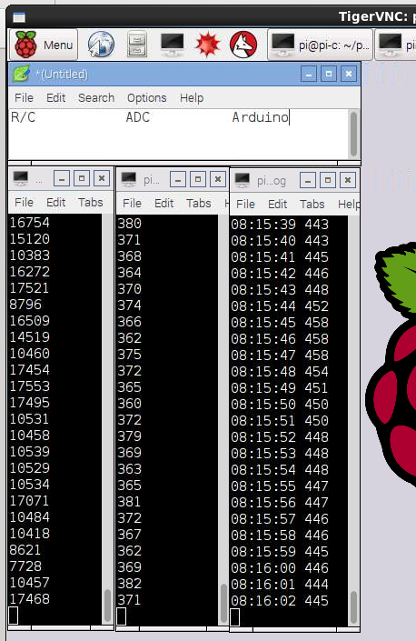
We are measuring the time it takes to charge the capacitor to a
value that the Pi sees as True. More when we talk about the
code.
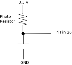 4.7 micro farads. Should probably be less but
that's what I had.
4.7 micro farads. Should probably be less but
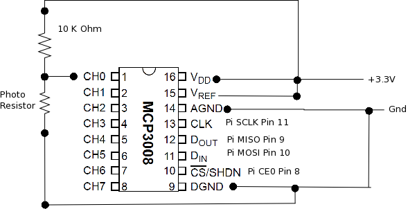
that's what I had.Here we are measuring voltage. 0 to 3.3 volts. This is what the ADC chip does.
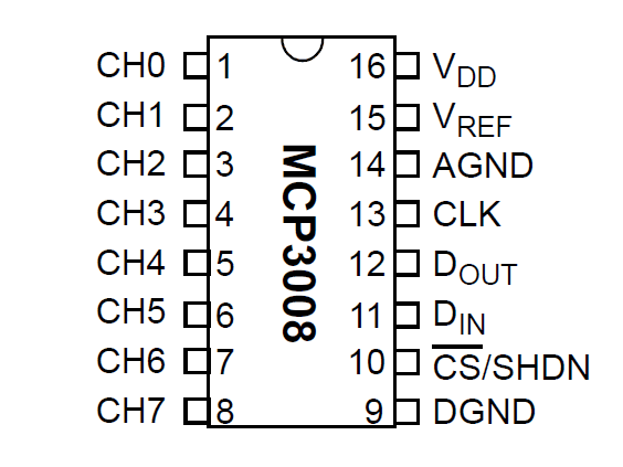

Note in the above schematic the photo-resistor and a 10 K Ohm
resistor are in series between 3.3 V and Ground. The analog
reading is taken from the junction between the two
resistors. This type of circuit is called a voltage divider.
About SPI - The Serial Peripheral Interface (SPI)
bus is a synchronous serial communication interface specification
used for short distance communication, primarily in embedded systems. Thanks
Wikipedia

Raspberry
Pi
ADC Chip
The SPI bus specifies four logic signals:
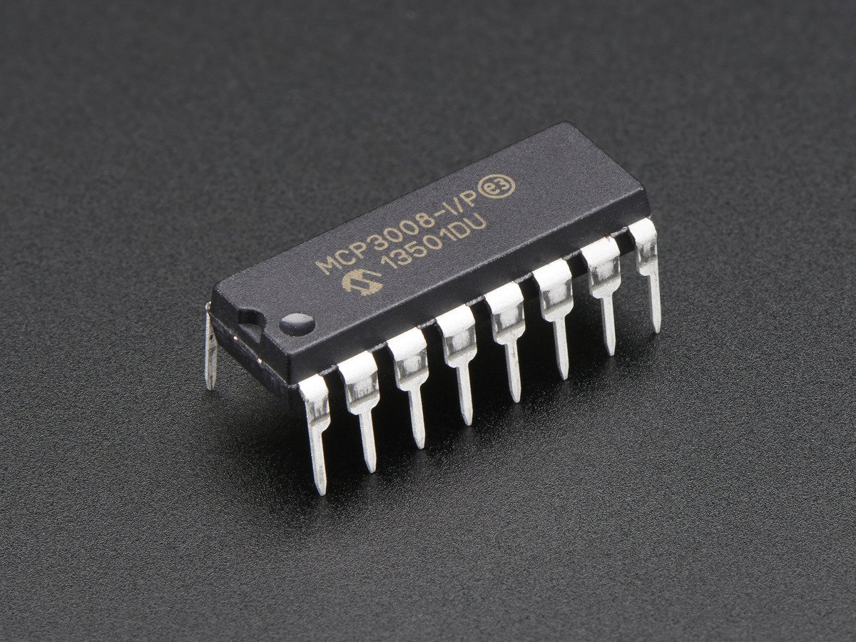
More detail? https://cdn-shop.adafruit.com/datasheets/MCP3008.pdf
#! /usr/bin/python
# Simple example of reading the MCP3008 analog input channels and printing
# them all out.
# Author: Tony DiCola
# License: Public Domain
# Modified to just use channel 0. Deid Reimer
import time
# Import SPI library (for hardware SPI) and MCP3008 library.
import Adafruit_GPIO.SPI as SPI
import Adafruit_MCP3008
import RPi.GPIO as GPIO
GPIO.setwarnings(False)
GPIO.setmode(GPIO.BCM)
lightPin = 5
GPIO.setup(lightPin, GPIO.OUT)
# Software SPI configuration:
#CLK = 18
#MISO = 23
#MOSI = 24
#CS = 25
#mcp = Adafruit_MCP3008.MCP3008(clk=CLK, cs=CS, miso=MISO, mosi=MOSI)
# Hardware SPI configuration:
SPI_PORT = 0
SPI_DEVICE = 0
mcp = Adafruit_MCP3008.MCP3008(spi=SPI.SpiDev(SPI_PORT, SPI_DEVICE))
# Main program loop.
while True:
value = 0
# Read the specified adc channel, display it then sleep for a bit.
value = 1023 - mcp.read_adc(0)
print value
if value < 300:
GPIO.output(lightPin, 1)
elif value > 700:
GPIO.output(lightPin, 0)
time.sleep(1)
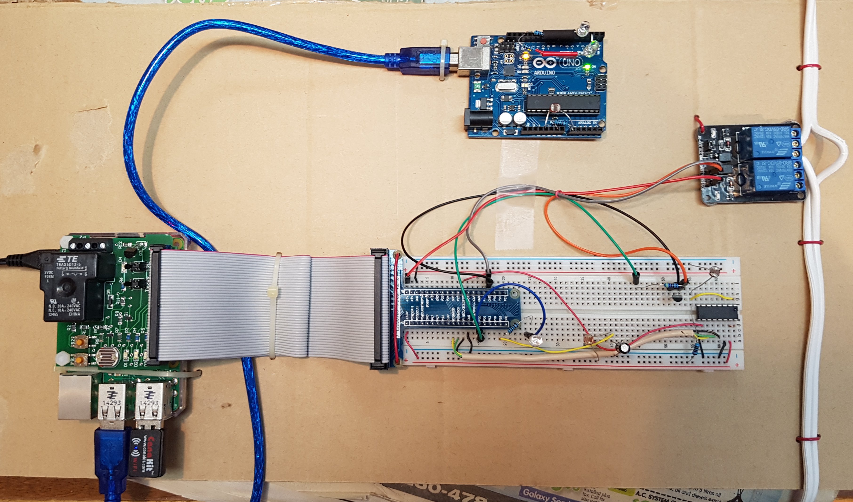
The voltage divider circuit shows up again. 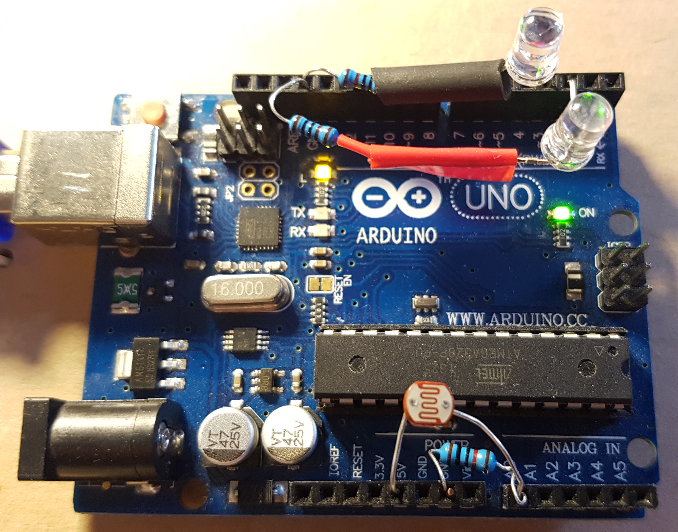
Using the Arduino is sort of cheating as it does ADC
natively. The interesting thing here is getting the
information back to the Pi.
/*
AnalogReadSerial
Reads an analog input on pin 0, prints the result to the serial monitor.
Attach the center pin of a potentiometer to pin A0, and the outside pins to +5V and ground.
This example code is in the public domain.
*/
// the setup routine runs once when you press reset:
void setup() {
// initialize serial communication at 9600 bits per second:
Serial.begin(9600);
}
// the loop routine runs over and over again forever:
void loop() {
// read the input on analog pin 0:
int sensorValue = analogRead(A0);
// print out the value you read:
Serial.println(sensorValue);
delay(1000); // delay in between reads for stability
}
#! /usr/bin/python
import serial, time
# Instantiate an instance of serial for the connection
# to the Arduino.
ser = serial.Serial('/dev/ttyACM0', 9600)
# Loop forever reading and displaying the serial input
# from the Arduino.
while True:
inval = ser.readline()
theTime = time.strftime("%H:%M:%S")
print theTime + " " + inval.strip("\n")