
SSID: Steele
PW: Piwehavelotsof.
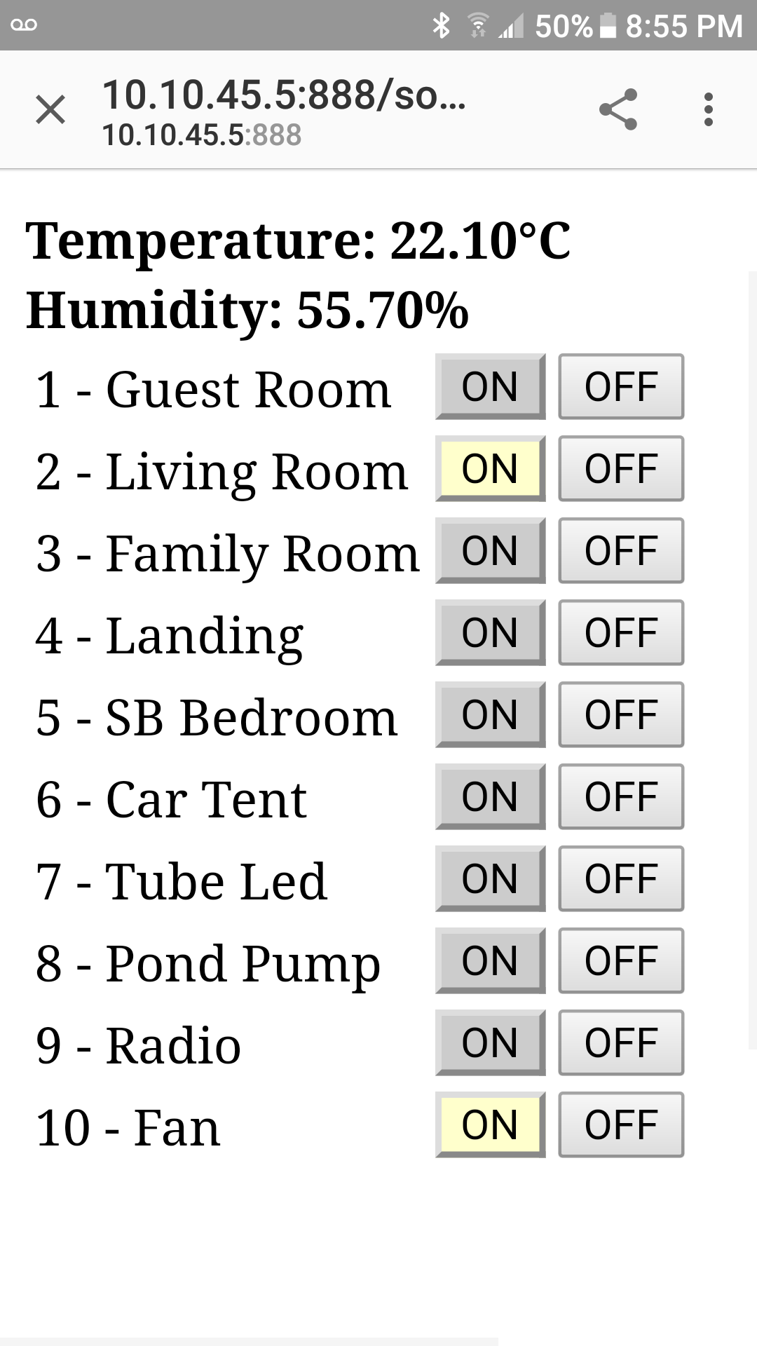
10.10.45.5:888 to connect to the esp8266 web server.
ID: light
PW: makeBright
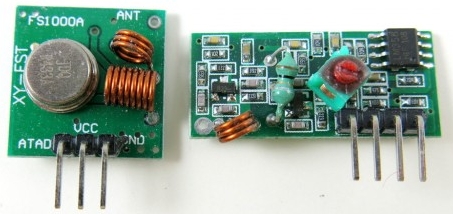
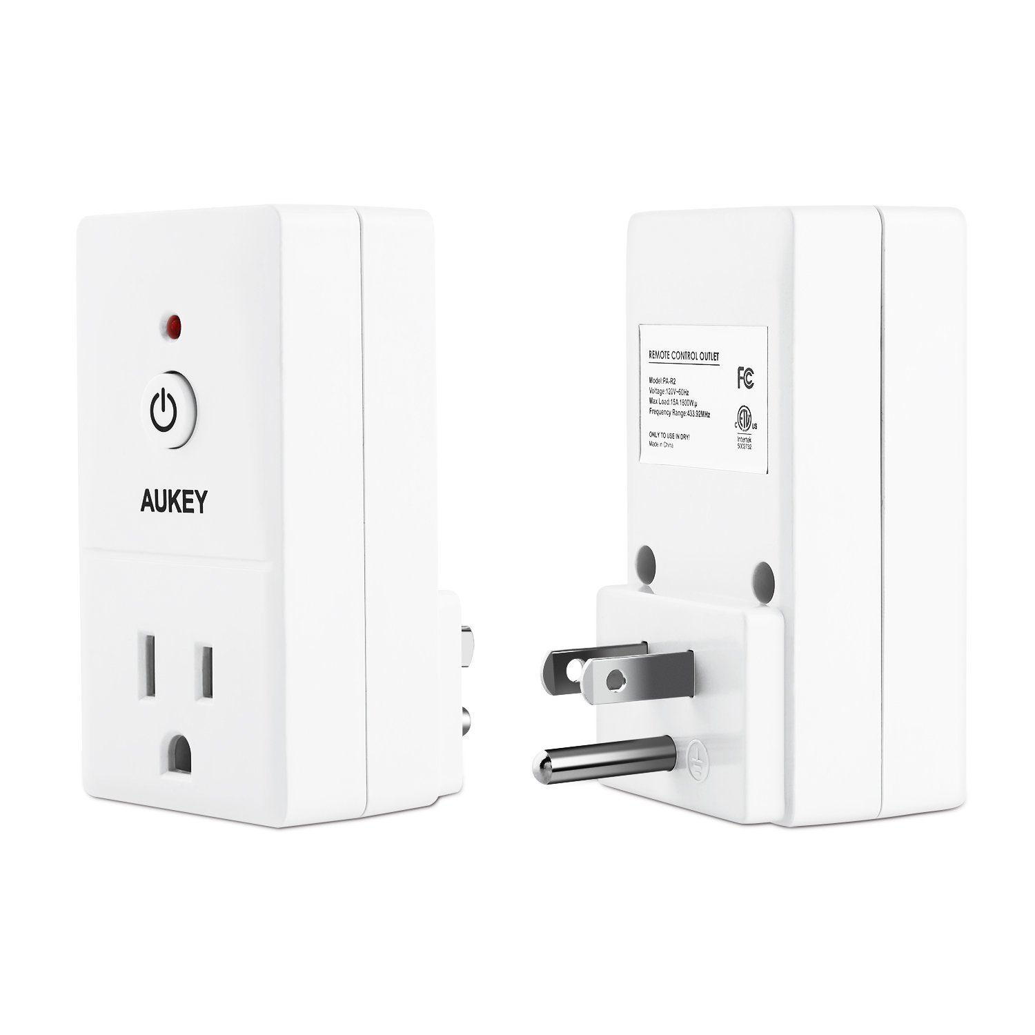
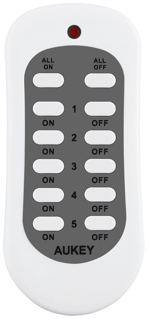
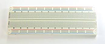
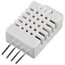
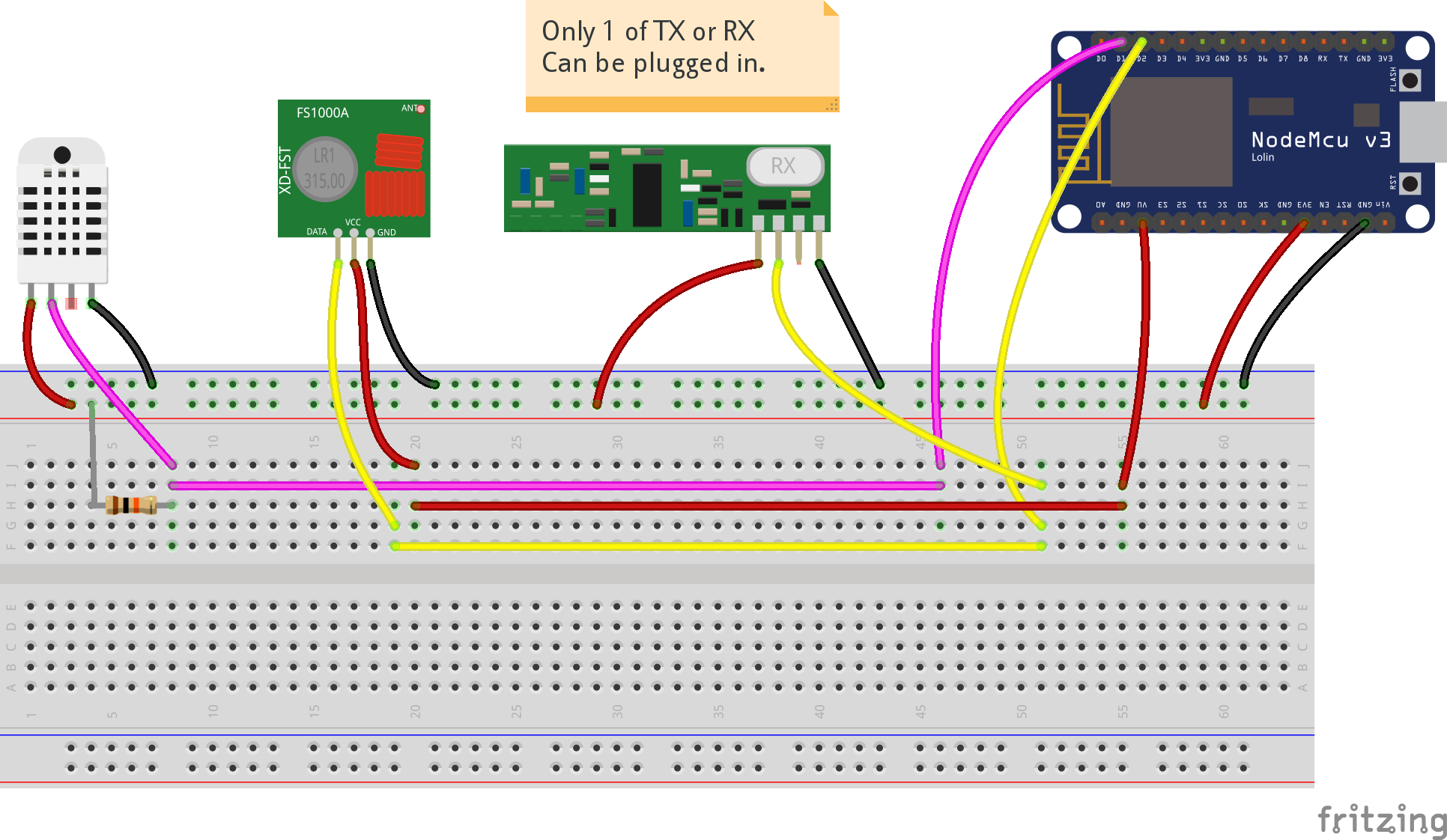
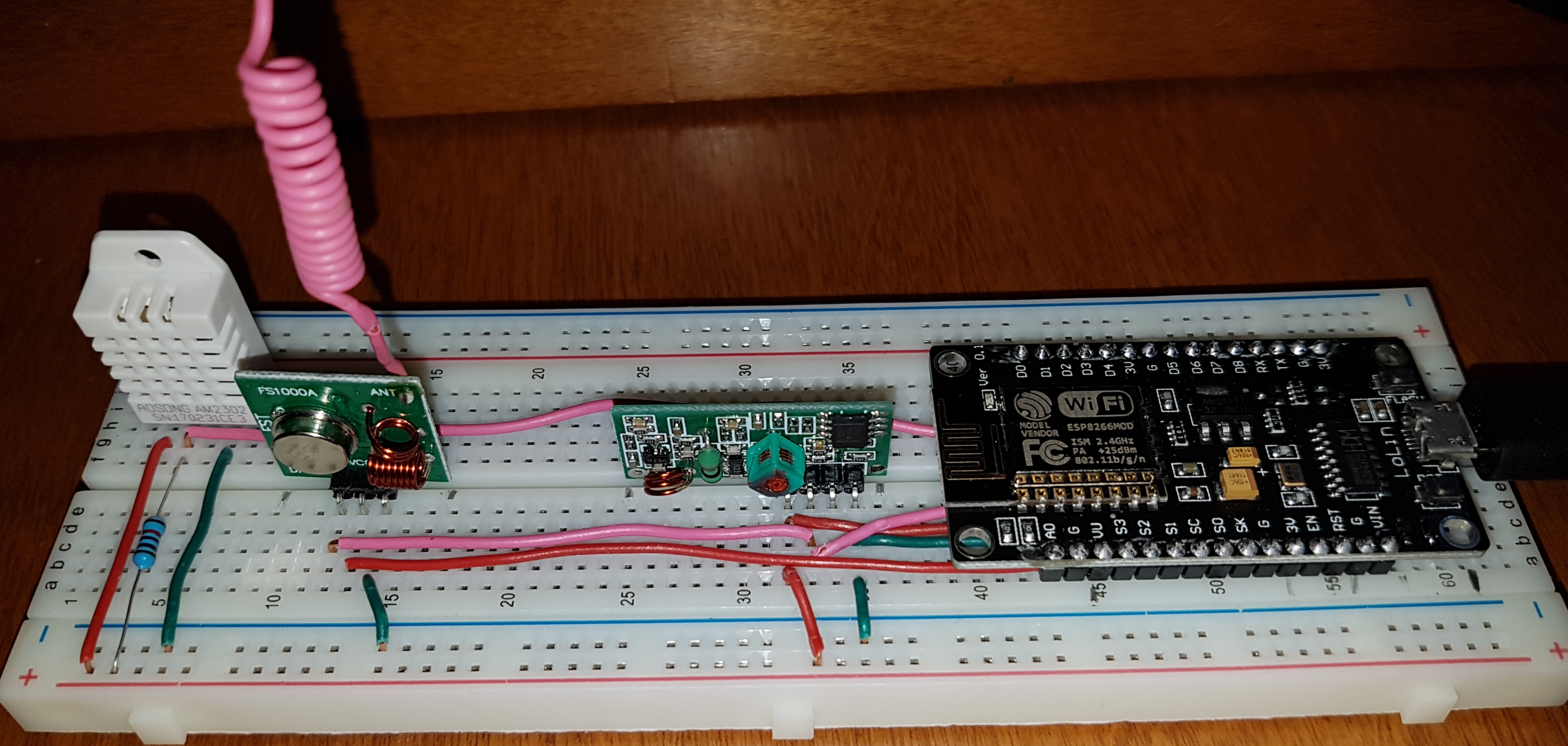
Note that the Plus (VCC) supply is 3.3 volts for the receiver and
5 volts for the transmitter. This is because the ESP8266
expects 3.3
volts on its pins so the voltage supplied to the input pin reading
the received data needs to be 3.3 volts. 5 Volts would fry
the 8266.
We can give the transmitter 5 Volts on the supply as this voltage
does not get to the 8266. The greater voltage gives the
transmitter
more power thus more range.

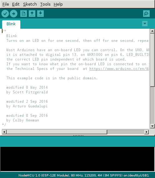
These are part of the ESP 8266 base - we
don't need to add these.
<ESP8266WiFi.h> Supports the wifi
connection
<WiFiClient.h> Supports a wifi connected client.
<ESP8266WebServer.h> Web Server Module
We need to add these:
<RCSwitch.h> 433 MHz
receiver/transmitter
<DHT.h> Temperature/humidity sensor -
ask about
this later if you care.
Normally we simply push a button but as seen above we have
software to do this for us. But what does the software have
to send

The RCSwitch.h library comes with an example that you will find
in the directory:
~/Arduino/libraries/rc-switch-master/examples/ReceiveDemo_Advanced
There are two file in here:
The ReceiveDemo_Advanced program calls the output code. If
you run this on the Arduino, the Receive... program seems to find
the output program. On the ESP8266 it does not. So I
just combined the two into a single file. That works.
receive.c.pdf
I used the binary values. Bolded here.
To get these I held the remote next to the receiver and pushed a
button and got:
Decimal: 5147919
(24Bit) Binary: 010011101000110100001111
Tri-State: not applicable PulseLength: 308 microseconds
Protocol: 1
Raw data:
9570,306,883,880,303,295,890,294,888,876,310,871,313,869,315,285,897,870,314,288,892,293,888,295,889,293,890,874,313,286,899,868,315,283,901,284,897,286,895,287,902,864,317,866,318,864,321,862,319,
Decimal: 5147915 (24Bit) Binary: 010011101000110100001011
Tri-State: not applicable PulseLength: 308 microseconds
Protocol: 1
Raw data:
9566,308,878,888,294,304,881,303,884,883,301,881,303,880,303,295,887,880,304,295,890,293,889,294,887,296,891,876,304,294,893,875,307,291,894,290,891,291,893,291,891,876,306,292,893,873,307,876,303,
Copy the binary values and put them into the
transmit program discussed above. The array variable
sockets contains the codes.
char sockets[20][25] = {
"010101101000110100001111", // On
"010101101000110100001110", // Off ...
"010101101000110100001101",
"010101101000110100001100",
"010101101000110100001011",
"010101101000110100001010",
"010101101000110100000111",
"010101101000110100000110",
"010101101000110100000101",
"010101101000110100000100",
"010011101000110100001111",
"010011101000110100001110",
"010011101000110100001101",
"010011101000110100001100",
"010011101000110100001011",
"010011101000110100001010",
"010011101000110100000111",
"010011101000110100000110",
"010011101000110100000101",
"010011101000110100000100",
};
There are 10 switches in the system and 20 codes. On and
off for each switch.
