PL9823 Web Controlled LEDs
Introduction
We thought we would start with something a bit whimsical.
Since we are early in the academic year

This all started when my my wife decided that we should do
something with the 60 or so telephone insulators she has been
collected for the past 30+ years. Perhaps put a led in them
and stick them in the garden she suggested.
So ... I went looking on Ali Express for cheap LEDs.
Thinking a bunch of different coloured LEDs would be fun.
And I found:

- Not only are the LEDs any colour I want, they can be
any of 16 million or so colours. And they are individually
addressable. Each led in the circuit can be a different
colour and the colours can change.
- So I bought 100 of them!
- Then over the next several days - with much reading of web
pages and tutorials and libraries - I managed to get them to
work.
Thanks to:
And I built the following. The real thing is
wandering about here somewhere with a battery attached to it.
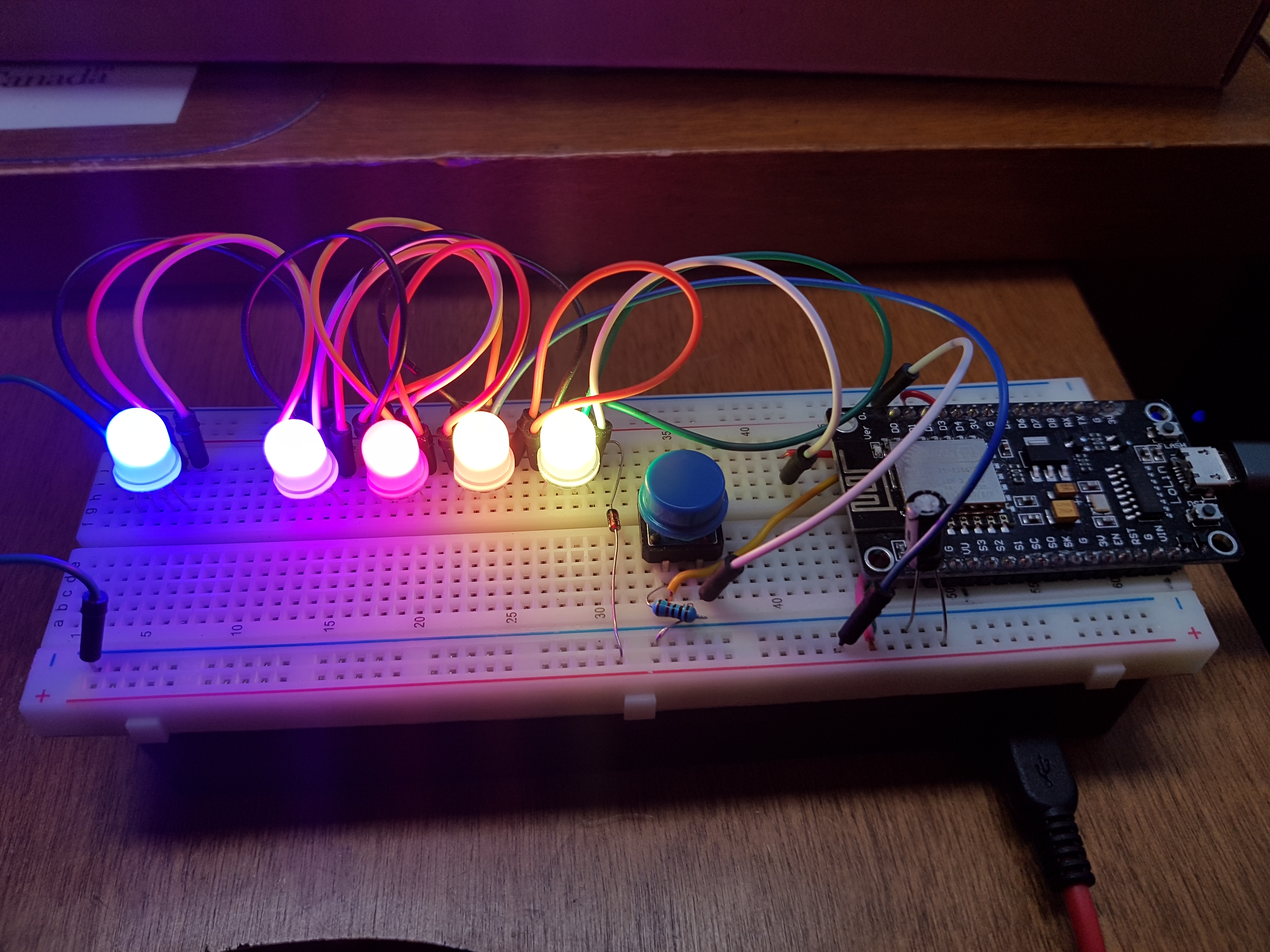
- The NodeMCU
ESP8266 micro-controller runs the show
- The push button cycles through the various led programs that I
wrote
- The LEDs, of course, light up
- And the prototype board holds it all together and provides
electrical connections
I then spent the next month off and on writing led "programs" so
that pushing the button does something.
- I currently have 8 programs that flash the lights in various
ways,
- obviously, there are an infinite number of
possibilities.
- If you changed the layout of the LEDs to say - a grid - you
could show pictures ...
It then occurred to me that use a web page could web control the
selection of light program.
- Thanks to the ESP8266s built in wifi and web server.
- So I did
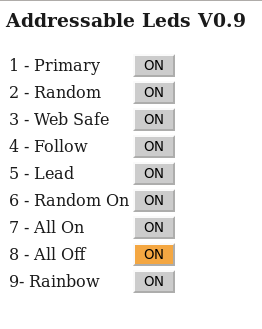
Credentials
URL is: 10.10.45.10
ID: pl9823
PW: neopixelnot (neopixel belongs to adafruit)
If you want to control the lights you need to be connected to
the Steele ssid (wifi network).
Details
Code
And there is a problem. We put a password on the request
to get the web page to change the lights but look:
Anyone with network packet analyzer like wireshark can see the ID
and Password!
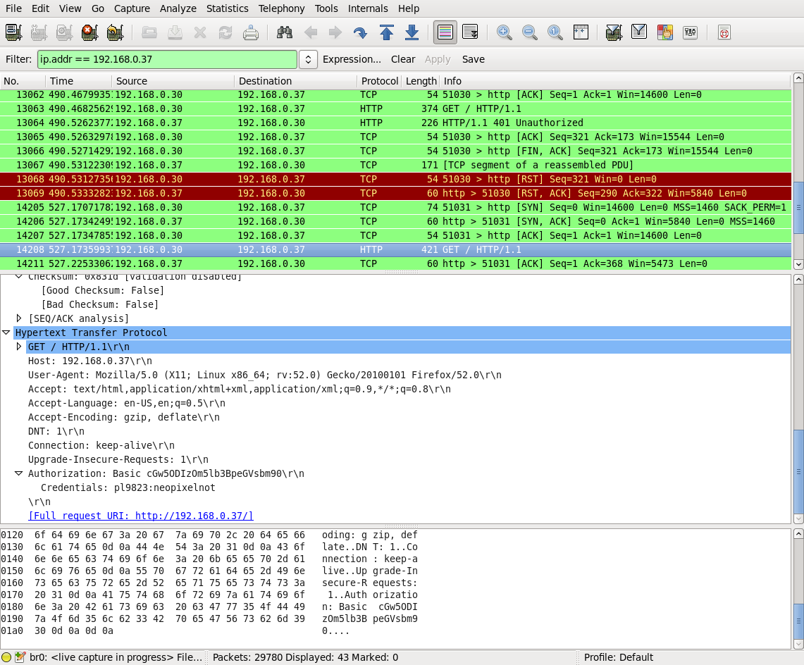
And then the web page is displayed

HTTPS vs HTTP
- The simple answer to this problem is instead of doing
http:// We do https:// ... But we can't because the
ESP8266 does not do https.
- Then, of course you ask the question - who cares if my lights
get change by some hacker. And the answer is probably
nobody. But this is an example of Internet of Things (IOT)
and the Things are often much more critical that whimsical
flashy lights Things like:
- Live Billboards - you might not get paid if someone draws a
mustache on the local politician
- Pond pumps - could flood your yard and kill your goldfish
(real story, but probably not a hacker).
- Room lights
- Greenhouse control
- Pacemakers

- Predator Drones
 Just sayin...
- ...
Our proposed solution is to create a middle man to handle
https. So the http is only on a LAN, not the less forgiving
WAN.

More on security next time.
Hardware
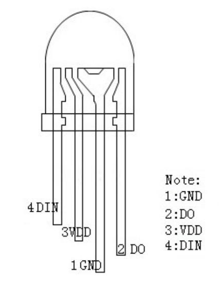
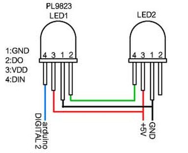

Block Diagram showing controller chip, LEDs and how they
are daisy chained.
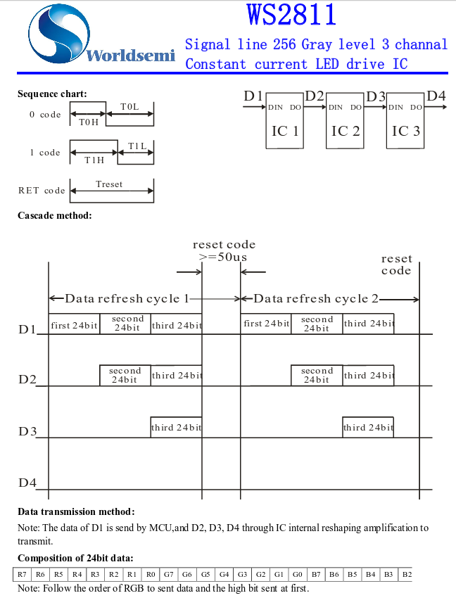
Data flow. The way these PL9223 and other addressable led devices work is
that 24 bits for each of the led RGB colours are sent down
the data wire. So in the case of 5 LEDs, 24 x 5 = 120 bits
are sent from the ESP8266.
- The first led grabs the first 24 and latches them.
The remaining 96 are sent to the second led
- The second grabs the next 24 and the remaining 72 are sent
on.
- Etc. for all the LEDs in the chain.
NodeMCU ESP8266 Development Board
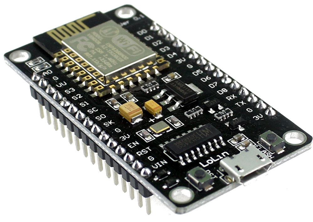
NodeMCU ESP8266
Schematic
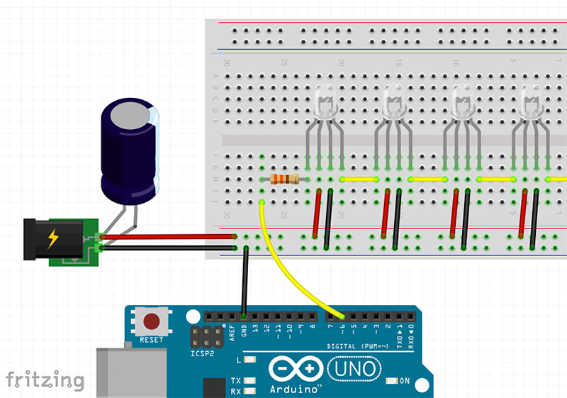
Controlling using a 5V Arduino
3.3 V ESP 3.3V vs 5V PL9823
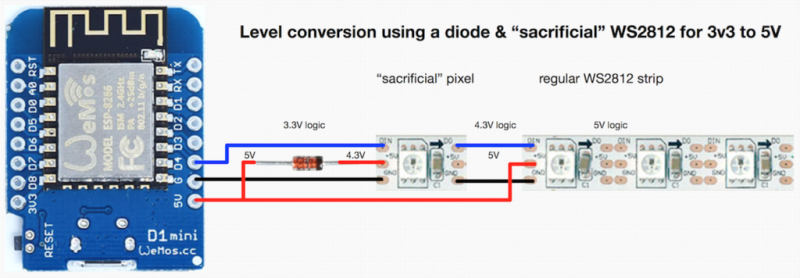
To control the 5 Volt WS2811 (and others) with an ESP8266 at 3.3
volts you need to shift the level.
The data sheet states that a logic high input will be detected
at a minimum voltage of 0.7 * Vcc. If you’re running the LED at
5V, this means 5 V * 0.7 = 3.5 V will be needed for the WS2811
to detect a ‘1’ on the data line. While you might get away with
using 3.3 V, after all the specification in the data sheet is
meant to be a worst case, it’s possible that you’ll run into
reliability issues.
To perform the level shift, a signal diode is placed in series
with the power supply of the first LED. This drops the first LED
to 4.3 V, which means a 4.3 V * 0.7 = 3.01 V signal can be used
to control it. The logic out of this LED will be at 4.3 V, which
is enough to power the rest of the LEDs running at 5 V.
This information came from hackaday.com.
Controlling using a 3.3V ESP8266
Button 
- The 50K Ohm resistor is called a pull up resistor. it
ensures that the Pi input pin is normally connected to 3.3
Volts. This ensures that the input is not
floating. If it were left floating then random
environmental electrical noise could cause the input to go
from 0 to 1, like, randomly. Because the
resistance is so high no significant current is flowing.
0.066 MilliAmps
- 1K Ohm resistor between the switch and the ground is
in case we accidentally set the pin to output rather than
input. This will limit the output current in case the
pin is set to output and the switch closed.
- You may need to debounce the input from a switch with some
logic or delays. As the switch closes there is a period
when it goes from open to closed a few times before it closes
solidly. The easiest way to do this is to delay a few
milliseconds before using a switch value. (https://en.wikipedia.org/wiki/Switch#Contact_bounce)
Are there topics you would like to see?


 Just sayin...
